使用 VisualShader
VisualShaders 是创建着色器的可视化替代方案。
由于着色器本质上与视觉效果有联系, 与纯粹基于脚本的着色器相比, 基于图的方式, 有纹理, 材质等的预览, 提供了很多额外的便利. 另一方面,VisualShaders并没有暴露出着色器脚本的所有功能, 对于特定的效果, 并行使用两者可能是必要的.
备注
如果你对着色器不熟悉,可以从阅读 着色器简介 开始。
创建 VisualShader
VisualShader 可以在任何 ShaderMaterial 中创建。要开始使用 VisualShader,请在你选择的对象中创建一个新的 ShaderMaterial。
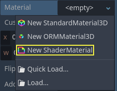
Then assign a Shader resource to the Shader property.
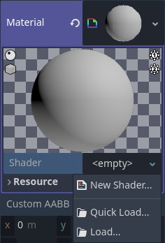
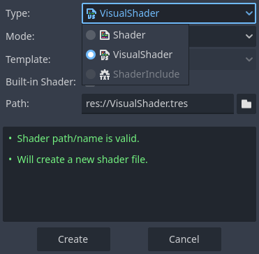
Click on the new Shader resource and the Create Shader dialog will
open automatically. Change the Type option to VisualShader
in the dropdown, then give it a name.
Click on the visual shader you just created to open the Shader Editor. The layout of the Shader Editor comprises four parts, a file list on the right, the upper toolbar, the graph itself, and a material preview on the right that can be toggled off
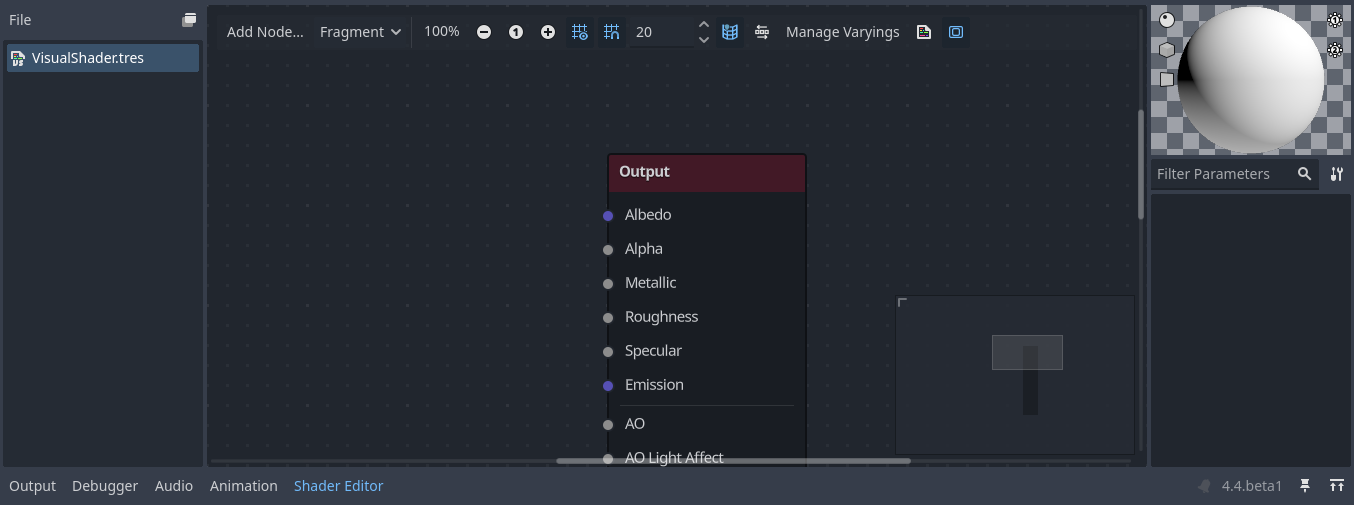
在工具栏中从左到右:
添加节点按钮会显示一个弹出式菜单,让你为着色器图添加节点。下拉菜单是着色器类型. 顶点, 碎片和光线和脚本着色器一样, 它定义了哪些内置节点将是可用的.
下面的按钮和数字输入控制缩放级别, 网格捕捉和网格线之间的距离(单位为像素).
The toggle controls if the graph minimap in the bottom right of the editor is visible or not.
The automatically arrange selected nodes button will try to organize any nodes you have selected as efficiently and cleanly as possible.
The Manage Varyings button opens a dropdown that lets you add or remove a varying.
The show generated code button shows shader code corresponding to your graph.
The last icon toggles the material preview on or off.
备注
虽然 VisualShader 不需要编码,但它们与脚本着色器有着相同的逻辑。建议学习这两者的基础知识,以便对着色管道有一个很好的理解。
可视化的着色器图形在场景后台转换为脚本着色器, 按下工具栏上的最后一个按钮就可以看到代码. 这可以方便理解特定节点的作用, 以及如何在脚本中呈现.
使用 Visual Shader 编辑器
默认情况下, 每个新的 VisualShader 都会有一个输出节点. 每个节点的连接都在输出节点的一个套接处结束. 节点是创建着色器的基本单元. 要添加一个新的节点, 点击左上角的 添加节点 按钮, 或者在图形中的任何一个空的位置上右击, 就会弹出一个菜单.
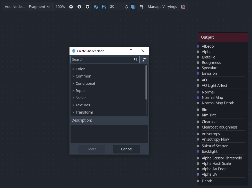
此弹出窗口具有以下属性:
如果你在图形上单击右键, 这个菜单将在光标位置被调出, 创建的节点, 在这种情况下, 也将被放在该位置, 否则, 将在图形的中心位置创建.
它可以在水平和垂直方向上调整大小, 以允许显示更多的内容. 尺寸变换和树的内容位置在调用当中被保存, 所以如果突然关闭了弹出窗口, 可以很容易地恢复它以前的状态.
下拉选项菜单中的
展开全部和折叠全部选项可用于轻松列出可用节点.你也可以从弹出式菜单中拖放节点到图形上.
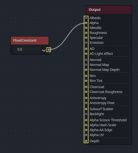
虽然弹出的节点是按类别分类的, 但一开始会不知所以. 试着添加一些节点, 将它们插入输出套接处, 观察会发生什么.
当把任何 scalar 输出连接到 vector 输入时, 向量的所有分量将取标量的值.
当把任何 vector 输出连接到 scalar 输入时, 标量的值将是向量分量的平均值.
可视化着色器节点界面
Visual shader nodes have input and output ports. The input ports are located on the left side of the node, and output ports are located on the right side of the node.
These ports are colored to differentiate type of port:
类型 |
Color |
描述 |
示例 |
|---|---|---|---|
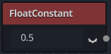
Scalar |
Gray |
标量是单个值。 |
|
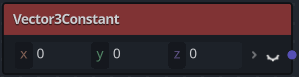
Vector |
紫色 |
向量是一组值。 |
|
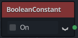
Boolean |
Green |
开关、真假。 |
|
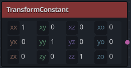
Transform |
Pink |
矩阵,常用于顶点的变换。 |
|
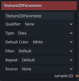
Sampler |
橙色 |
纹理采样器。可用于对纹理进行采样。 |
|
All of the types are used in the calculations of vertices, fragments, and lights in the shader. For example: matrix multiplication, vector addition, or scalar division.
There are other types but these are the main ones.
可视化着色器节点
以下是一些值得了解的特殊节点. 该清单并非详尽无遗, 可能会增加更多的节点和示例.
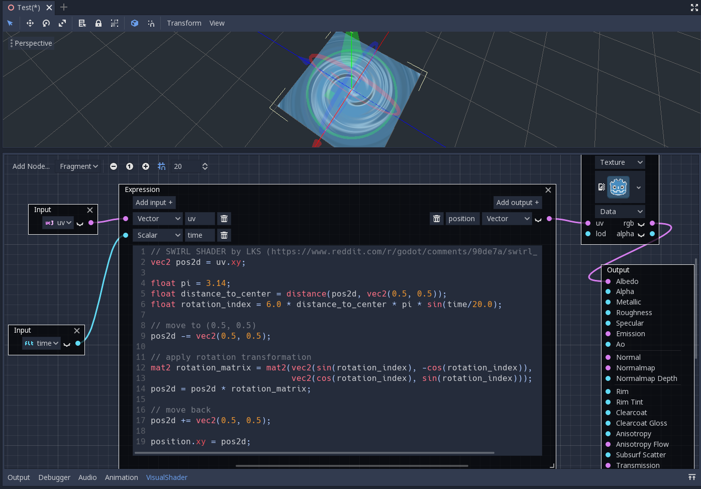
Expression 节点
Expression 节点允许你在视觉着色器中编写 Godot 着色语言(GLSL-like)表达式. 该节点具有添加任意数量的所需输入和输出端口的按钮, 并且可以调整其大小. 你还可以设置每个端口的名称和类型. 输入的表达式将立即应用于材质(焦点离开表达式文本框后). 任何解析或编译错误都将打印到 "输出" 选项卡. 默认情况下, 输出初始化为零值. 该节点位于 "特殊" 选项卡下, 可用于所有着色器模式.
这个节点的可能性几乎无穷无尽 —— 你可以编写复杂的过程, 并使用基于文本的着色器的全部力量, 例如循环, 关键字 discard , 扩展类型, 等等. 例如:
Reroute node
The Reroute node is used purely for organizational purposes. In a complicated
shader with many nodes you may find that the paths between nodes can make
things hard to read. Reroute, as its name suggests, allows you to adjust the path
between nodes to make things easier to read. You can even have multiple reroute
nodes for a single path, which can be used to make right angles.
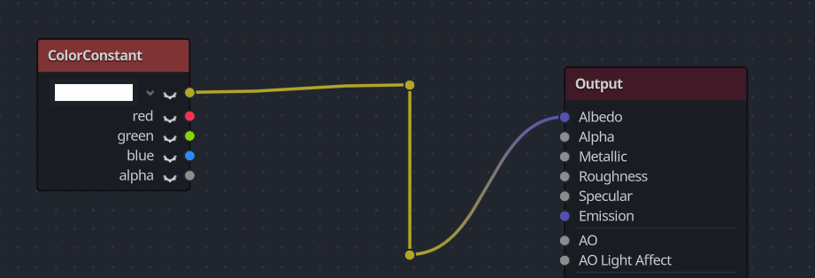
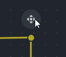
To move a reroute node move your mouse cursor above it, and grab the handle that appears.
Fresnel 结点
Fresnel 节点用于接受法线向量和视图向量, 并生成一个标量, 即它们之间的饱和点积. 此外, 你可以设置反转和方程的幂. Fresnel 节点非常适合为对象添加类似边缘的照明效果.

Boolean 节点
Boolean 节点可以转换为或 Scalar 或 Vector , 分别表示 0 或 1 和 (0, 0, 0) 或 (1, 1, 1) . 该属性可用于一键启用或禁用某些效果部件.
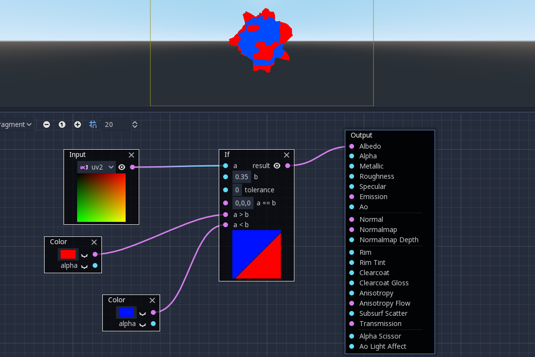
If 节点
If 节点允许你设置一个向量, 它将返回 a 和 b 之间的比较结果. 有三个向量可以返回: a == b (在这种情况下, 容差参数是作为比较阈值提供的--默认情况下它等于最小值, 即 0.00001 ), a > b 和 a < b .
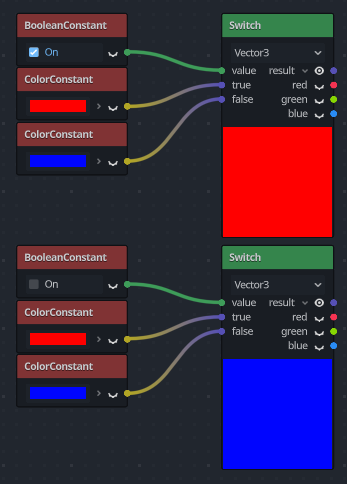
Switch 节点
The Switch node returns a vector if the boolean condition is true or
false. Boolean was introduced above. If you want to convert a vector
to a true boolean, all components of the vector should be non-zero.
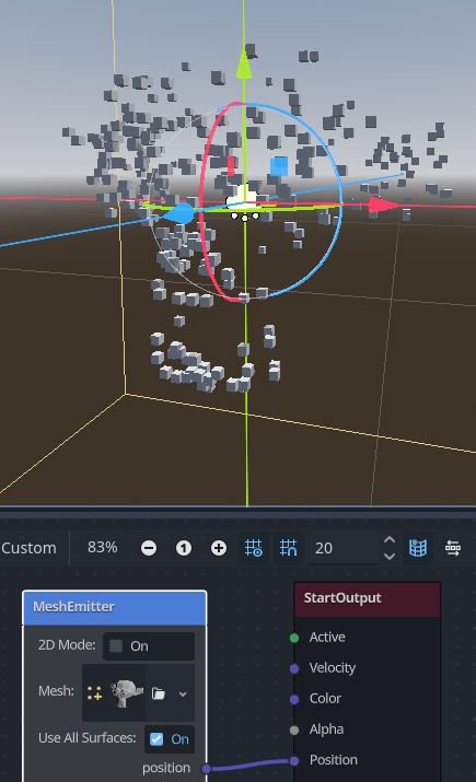
Mesh Emitter
The Mesh Emitter node is used for emitting particles from mesh vertices. This is
only available for shaders that are in Particles mode.
Keep in mind that not all 3D objects are mesh files. a glTF file can't be dragged and dropped into the graph. However, you can create an inherited scene from it, save the mesh in that scene as it's own file, and use that.
You can also drag and drop obj files into the graph editor to add the node for that specific mesh, other mesh files will not work for this.